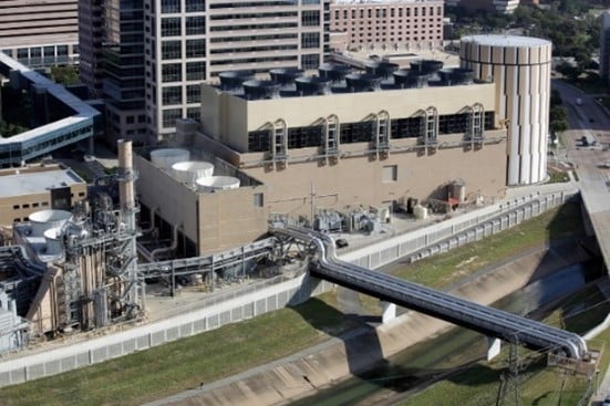
Thermal Energy Storage (TES) for chilled water systems can be found in commercial buildings, industrial facilities and in central energy plants that typically serve multiple buildings such as college campuses or medical centers (Fig 1 below). TES for chilled water systems reduces chilled water plant power consumption during peak hours when energy costs are highest. In this post we look at
- Basic design concepts
- Electrical power peak demand reduction

Fig. 1 Central Energy Plant at Texas Medical Center
TES Basic Design Concepts
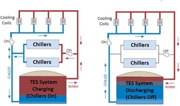
Thermal energy storage systems utilize chilled water produced during off-peak times – typically by making ice at night when energy costs are significantly lower which is then stored in tanks (Fig. 2 below). Chilled water TES allows design engineers to select individual energy plant chillers based on the average cooling load rather than the peak cooling load, reducing chiller size and the associated capital cost. Additional TES advantages include cost reductions realized by lower chilled water supply temperatures and higher HVAC cooling coil air differential temperatures (Delta T), resulting in smaller chilled water and HVAC air distribution equipment.

Fig. 2 TES chilled water plant schematic with ice storage tanks
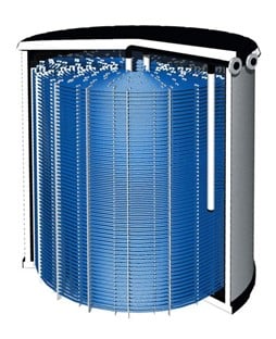
Chilled water TES acts like a battery for process and HVAC cooling loads. It uses standard cooling equipment with the addition of an ice-filled storage tank. The ice storage tank is insulated and contains internal baffles or diffusers to maximize heat transfer between the ice inside the tank and the entering and leaving chilled water (Fig. 3 below).

Fig.3 TES ice storage tank cut-away view
A mixture of 20-30% ethylene glycol and water is commonly used in TES chilled water systems to reduce the freezing point of the circulating chilled water and allow for ice production in the storage tank. Chilled water TES systems typically have a chilled water supply temperature between 39°F to 42°F but can operate as low as 29°F to 36°F depending on the glycol mixture, the chiller plant design and the specific needs of the facility process cooling loads and/or HVAC cooling loads.
TES Electrical Power Peak Demand Reduction
Energy savings through peak demand management is the key economic benefit in TES chilled water systems. In Fig. 4 below, the graphic on the left depicts a typical facility load profile where the chiller plant cooling electrical demand is more than 40% of the total electrical demand during the peak demand period. The graphic on the right shows an electrical demand reduction of 600 kW during the peak demand period made possible by removing the chiller electrical power consumption and utilizing ice storage to provide the required chilled water from 6 am to 6 pm. At the end of the peak demand period, the chiller plant is used to replenish the ice in the storage tank as well as provide the required chilled water to the facility process cooling loads and HVAC cooling loads between 6 pm and 6 am.

Fig. 4 Comparison of electrical demand before and after TES
The return on investment (ROI) for TES chilled water systems depends on multiple factors including the difference in off-peak and peak kWh electrical rates for the area. In general, it can take less than five years to realize the ROI of a TES chilled water system.
Interested in learning more?
VERTEX’s team of professional mechanical engineers have expertise with all aspects of chilled water plant design, operation, installation, and maintenance. We are available to analyze your specific chiller water plant performance, and help you identify potential power and capital equipment savings by utilizing TES. For more information, please contact me at rezold@vertexeng.com or The Vertex Companies LLC.


