


What is VRF?
VRF systems are quickly becoming the specified HVAC system of choice for residential, commercial, and industrial applications in the United States. VRF systems feature multiple zone flexible installations, and the lack of ductwork is a distinct advantage where space is limited making it an excellent choice for existing building HVAC system retrofits. Inverter technology allows for a variable speed compressor and the variable capacity of VRF systems is an excellent choice to meet both peak and part load demand as opposed to constant speed single capacity systems.
Air-Cooled VRF Systems – Two Types
Heat Pump VRF – 2 pipe system
Heat pump VRF systems, also known as 2-pipe VRF, allow heating or cooling in all indoor units but not simultaneous heating and cooling. Heat pump VRF systems are like split system heat pumps, but the major difference is an inverter driven compressor. The inverter driven compressor allows for a variable capacity system which more closely matches the true space load condition resulting in fewer starts and stops, reduced energy consumption, improved temperature and humidity control, and longer equipment life. Heat pump VRF systems typically include indoor ductless terminal devices that can be mounted on a wall, recessed in a ceiling or even mounted on the floor. When the indoor terminal units are in the cooling mode, they act as evaporators; when they are in the heating mode, they act as condensers.
Heat Recovery VRF – 3 pipe system
Heat Recovery VRF Systems, also known as 3-pipe VRF, allow heating and cooling in all indoor terminal devices simultaneously. Each outdoor air-cooled condenser is connected via 3 pipes to an indoor heat recovery unit: a high-pressure gas refrigerant line (for heating), a high-pressure liquid refrigerant line (for cooling), and a low-pressure gas suction line (for return to the outdoor unit). Each indoor heat recovery unit works together with the indoor terminal units and respective thermostats in each zone to determine if they require heating or cooling. An indoor terminal unit in heating mode is supplied with high-pressure gas refrigerant from the heat recovery unit. The heating mode indoor terminal unit acts like a condenser and the refrigerant exits as a high-pressure liquid and proceeds back to the heat recovery unit. The heat recovery unit combines high pressure liquid exiting heating zones with high pressure liquid from the outdoor condensing unit and directs it to any indoor terminal units that are in cooling mode. The cooling mode indoor terminal unit acts like an evaporator and the refrigerant exits as low-pressure gas, returns to the heat recovery unit, and then proceeds to the outdoor condensing unit to begin the cycle again.
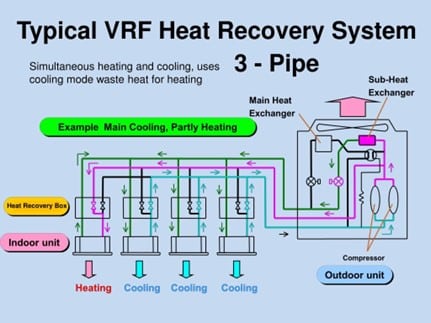
Figure 1: Typical VRF Heat Recovery System – 3 pipe
VRF Installation and Commissioning – Potential Issues
Refrigerant R-410A
Most of today’s VRF systems use R-410A refrigerant, achieving a very high energy efficiency ratio (EER) of 15 to 20 and integrated energy efficiency ratio (IEER) of 17 to 25. They are 20% to 30% more efficient than conventional HVAC systems due to partial load operation, speed modulation, zoning capabilities, and heat-recovery technology. The classification of R-410A in ASHRAE Standard 34-2019 is Safety Group A1 (meaning non-toxic and non-flammable), it has no ozone depletion potential, and it meets the stringent mandates of both the Montreal Protocol and the U.S. Environmental Protection Agency. However, due to its ability to displace oxygen, ASHRAE Standard 34-2019 has established the maximum refrigerant concentration limit (RCL) of R-410A to 26 lbs./1000 ft3 of room volume for occupied spaces. Additionally, the RCL of R-410A is reduced by 50% to 13 lbs./1000 ft3 of room volume for all areas of institutional occupancies in accordance with ASHRAE Standard 15-2019.
Piping
For best results, VRF system refrigeration piping should be constructed of copper tube, ASTM B 75, UNS C12200, H55 Temper (Light Drawn) for straight lengths, and ASTM B 280, UNS C12200, O60 Temper (Soft Annealed) for coiled. The three basic principles for refrigerant piping installation include dry, clean & tight. Great care must be taken during installation to prevent moisture from entering the refrigerant piping, no dust or contaminants must be allowed to enter, and of course it must be installed tight with no refrigerant leaks. Refrigerant piping ends should always be covered when stored or during installation, and piping should never be stored on a floor but rather on racks or shelving at the construction site. Refrigerant piping should be installed with a slight upward gradient toward the outdoor air-cooled condensing unit to prevent the build-up of refrigerant oil in low lying pockets, and piping supports should be installed as to not crush or otherwise damage the piping insulation. Pipe supports on horizontal piping runs should be a minimum of 5’ on center for piping with an outer diameter (OD) < 3/8” and up to 6.5’ on center for piping with an OD > ½”. Also, piping supports adjacent to flared fittings should be no more than 1’ away from the fitting to reduce the stress on the solder joint during VRF system operation.
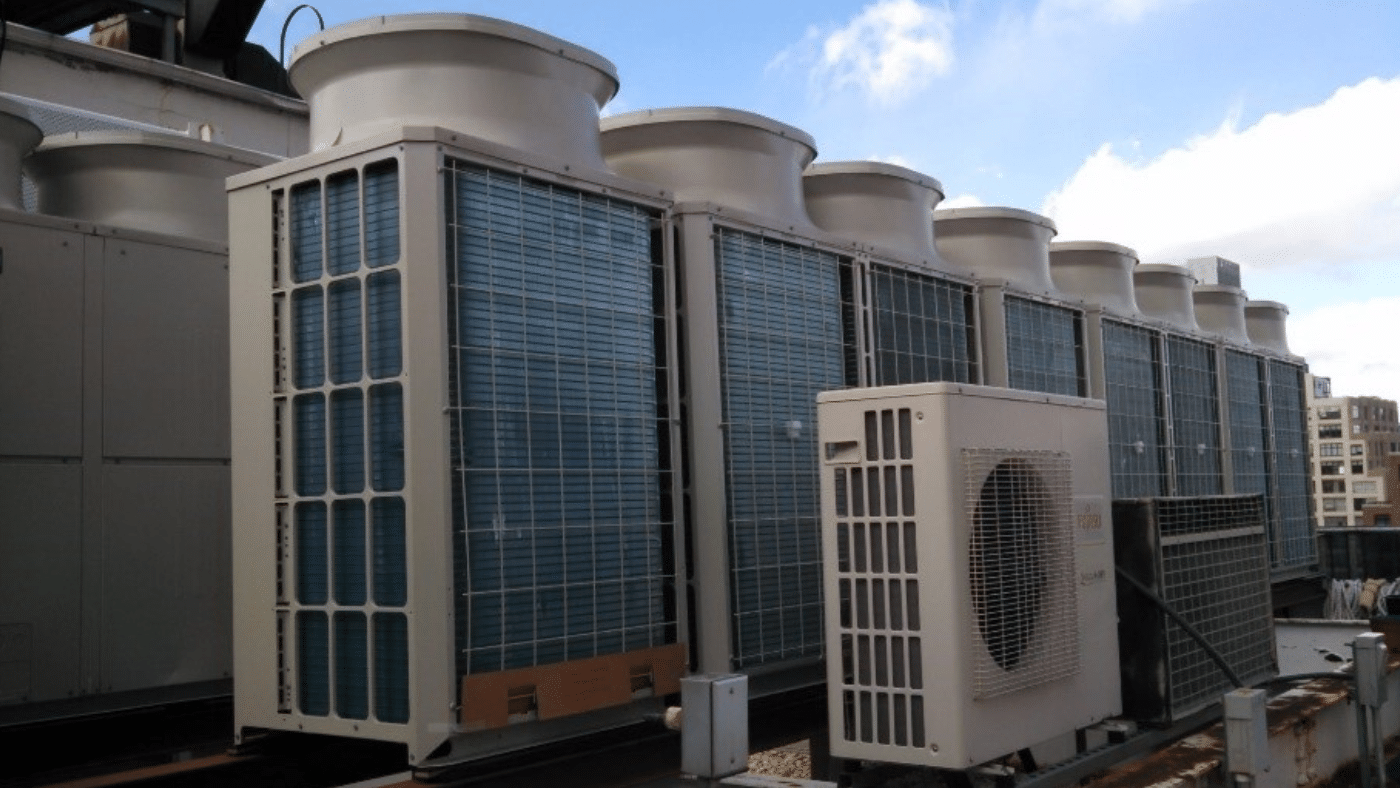
Outdoor Air-Cooled Condenser
Proper installation of outdoor air-cooled condensing equipment is critical to ensure that the VRF system performs to its specified capacity. Always refer to the manufacture’s installation literature for installation specifics but as a best engineering practice always allow adequate spacing between each condensing unit to ensure proper cooling air flow and space for equipment maintenance. Condensing units must always be mounted high enough above the ground or roof deck to allow for possible snow accumulation during the winter months. An 18” clear height for snow accumulation avoidance is typical but it depends on the location of the installation. Additionally, for roof mounted installations, wind loads must be properly considered and fasteners for mounting properly selected to ensure a safe installation. As mentioned previously, always refer to the manufacture’s installation literature to be certain that your outdoor air-cooled condensing equipment is properly installed.
VRF Piping Diameter and Length – Design Adherence During Field Installation
To ensure proper operation and performance of your VRF system, most VRF suppliers will provide a system piping diameter and piping length schematic which should be followed by the installation contractor in the field. The example schematic below features an LG Air Conditioner Technical Solutions (LATS) diagram that shows the outdoor air-cooled condensing unit, an indoor branch box, and multiple fan coils inside the building. Note that piping diameters and allowable piping lengths are shown which are essentially a roadmap for successful assembly by the installing contactor. The LATS diagram also shows the quantity of refrigerant in the system and the design heating and cooling loads which will all be verified during the commissioning process during initial system startup.
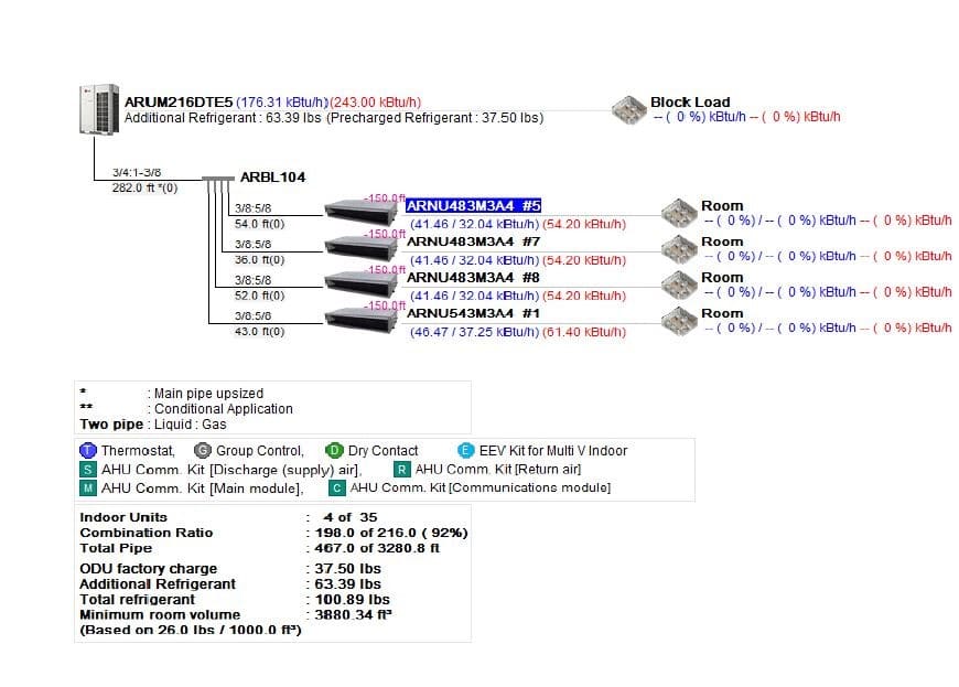
Figure 2: LATS Diagram
VRF Pipe Assembly – Brazing with Nitrogen Purge and System Pressure Testing
During brazing of copper VRF piping in an oxygen rich environment, cupric & cuprous oxides will form. On cooling these oxides flake off the inside of the copper VRF piping to form scale. Scale present inside copper VRF piping after assembly will be distributed throughout the system potentially fouling compressors, electronic expansion valves (EEVs), and could lead to premature equipment failures.
To prevent oxide formation and issues with scale, nitrogen, which is inert and non-reacting, is used during brazing to displace the oxygen and prevent scale formation. Typically, nitrogen is introduced into the VRF system through the Schrader valves at the outdoor air-cooled condensing unit or other convenient system access points. Typical flow and pressure for nitrogen purge during brazing are 2-3 CFH and 1-2 PSI, respectively.
Following successful brazing with nitrogen purge, VRF system piping should be pressure tested before put into operation. A typical VRF piping testing protocol includes holding 150 PSI for 3 minutes, followed by an increase in pressure to 325 PSI for holding for 5 minutes, and finally an increase in pressure to 550 PSIG and holding for 24 hours. Check with your specific manufacture’s installation literature to be certain that your pressure testing procedure meets or exceeds the manufacture’s requirements.
VRF System Commissioning
Once your VRF system has been properly installed, and the system piping has been verified “leak-free”, it’s time to introduce the refrigerant into the system and verify proper operation. Depending on the volume of VRF system piping, an appropriate refrigerant charge, typically in lbs., is calculated and verified during introduction. Some key aspects of VRF commissioning include:
- VRF fan coils are tested in both heating in cooling mode to verify proper response to zone thermostat set points.
- A full test and balance (TAB) report for each fan coil, all building exhaust, and all building make up air is completed to verify that the entire VRF system is operating in accordance with the design basis.
- The amperage draw on each VRF compressor motor is measured and verified to be in accordance with manufacture’s specifications.
- The building automation system (BAS) for the VRF system is tested to ensure that each control point functions and responds in accordance with the design basis.
- A VRF system commissioning report is generated and provided to the owner. The VRF commissioning report documents the proper operation of the entire VRF system at delivery and also indicates the required preventive maintenance for all aspects of the VRF system to the owner.
- VRF system operational training is also provided to the owner during the commissioning/delivery process and is a key part of VRF system operational success. It’s imperative that the owner fully understands the operational aspects of the system and the frequency of preventive maintenance activity.
Interested in learning more?
VERTEX’s team of mechanical engineers have expertise with all aspects of VRF system design, operation, installation, and commissioning. We are available to review your VRF system and help you identify issues which could lead to VRF system component failures. For more information, please contact our team at vertexeng.com/contact-us/.
Author: Rob Ezold